ARRL Antenna Book
This web page is for information that extends or supports the ARRL Antenna Book beginning with the 22nd edition. The section for each edition contains links to supplemental files and software, non-ARRL documents, and errata and corrections. To purchase the book, click here or browse to the ARRL Store where you can also find numerous other publications on antennas and transmission lines.
Information in support of previous editions can be found on the ARRL Product Notes page.
Printed-circuit boards for many current and previous Antenna Book projects are available from FAR Circuits.
Antenna Book Editions
-
Some readers have reported problems reading the CD-ROMs on Windows XP Professional machines. (This is not a problem on Vista or Windows 7.) The following problem description identifies the issue:
CD-ROM Drive May Not Be Able to Read a UDF-Formatted Disc in Windows XP. Your computer cannot read some or all files on CDs or DVDs that were recorded through the use of the Optical Storage Technology Association (OSTA) Universal Disk Format (UDF) file system standard. Symptoms may include: The disc is not recognized at all.
Microsoft has a well-documented support page for CD and DVD drive problems. Running the Microsoft Fix It application associated with this problem should take care of the problem.
Windows 7 limits on the length of filename paths is also sometimes exceeded. A possible workaround is as follows:
Create a directory file folder called Data Files. Within this folder create the file folder Yagi. Into this folder copy the entire contents of the YW (Yagi for Windows) folder from the hard disk. Therefore, the path now is C:>data Files>Yagi>filename.YW. The program should now work without need for the CD disk.
Another possibility is to transfer the files to a removeable USB thumb drive.
(Thanks, Zack W1VT)
Windows 7 and Security Issues
Windows 7 users also report problems opening files associated with some of the Antenna Book software, such as YW (Yagis for Windows). For example, “The file ‘510-24H.YW’ has an error. Examine it with a word processor.”
This is a file permission problem with operating systems released after Vista, not a 32/64 bit issue. (Additional information is available at www.arrl.org/faq-s.)
The good news is, most of the software runs just fine, once you get past the security issues. Due to issues with hackers writing malicious programs, Microsoft has implemented tougher measures to prevent hackers from gaining control of your computer. In order for programs like Yagi for Windows to write and modify files, so you can save your work, you need to explicitly grant the programs Administrative Privileges, by clicking the appropriate box in the security window for the program. Merely operating the program from an administrative account ("Run As Administrator") won’t allow the program to function properly.
This can be a little confusing, as the computer will flag the data file as the problem—changing the settings on the file won’t help. You need to change the settings for the program.
You may also download these software notes from the 21st edition with additional information about the Antenna Book's companion software.
The installer program creates several icons on the desktop during the install process. These icons all have similar names and it can be difficult to determine the correct shortcut. The names of the shortcuts can be edited by right-clicking the icon and selecting "Rename". The name can then be changed to something more descriptive in a few characters that are displayed with the shortcut. For example, "AntBk Content" for "Antenna Book Content".
The CD-ROM that comes with the ARRL Antenna Book includes the following software:
- EZNEC-ARRL - antenna modeling software by W7EL, based on EZNEC 5.0
- HFTA - terrain analysis software by N6BV, including propagation prediction files
- TLW - transmission line analysis software by N6BV
- YW - Yagi for Windows by N6BV to predict antenna performance
- SCALE - an antenna re-scaling program (included with the YW software)
EZNEC-ARRL included with the Antenna Book's 22nd edition is a special version of EZNEC 5.0 - its primary purpose is to enable viewing and analysis of the example antennas included with the Antenna Book. It operates as a normal EZNEC demo program except when a specially "signed" EZNEC description file (included on the Antenna Book CD) is opened. When analyzing a "signed" file, EZNEC-ARRL becomes a fully functional just like the standard EZNEC software. "Signed" files can be modified in any way and analyzed with full standard EZNEC program capability. However, EZNEC-ARRL will revert to demo operation when any file saved by EZNEC-ARRL, including a modified "signed" file, is re-opened. Any version of EZNEC-ARRL (including the versions from previous Antenna Books) will function with "signed" files from any Antenna Book edition and all EZNEC model files are compatible with all EZNEC program types. No other "signed" files are available except the ones furnished with the Antenna Book, and EZNEC-ARRL can be obtained only by purchasing the Antenna Book.
HFTA - see the Supplemental Information and Tools window below for notes on the HFTA instructions and operating with MicroDEM data.
Readme - this is the installation and operation instruction document that comes with the Antenna Book software.
Chapter numbers refer to the primary chapter in the ARRL Antenna Book that references the software.
Chapter 4 - Radio Wave Propagation
RngBrg.ZIP - software to compute the range and bearing from a point at one latitude/longitude to another.
Chapter 7 - Log Periodic Antennas
Log Periodic Element and Phase Line Calculator - Spreadsheet to calculate LPDA element lengths and spacings, along with phase line impedance, by Dennis Miller, KM9O. This spreadsheet is in Excel format (XLS) and was last updated on 12 Sep 2011.
Chapter 8 - Multielement Arrays
Arrayfeed1.zip - Phased array feed system design software by W7EL. This package has been updated from the version supplied with the 21st edition. The ZIP file contains a help file (Arrayfeed1.chm) and the software (Arrayfeed1.exe).
Chapter 11 - HF Yagi and Quad Antennas
GAMMA2-1.ZIP - An MS-DOS utility that computes gamma match network values. The compressed ZIP file contains GAMMA2-1.BAS (BASIC source code that can be run with GWBASIC or QBASIC) and the compiled GAMMA2-1.EXE.
GAMMAMW4.ZIP - An improved version of GAMM2-1.ZIP that corrects a calculation problem that fails to find solutions to the calculations when the combination of the desired feed line impedance exceeds the product of the raw antenna resistance and the gamma step-up value.. The code was developed by Bill Wortman, N6MW and generously donated to the ARRL and the readers of the Antenna Book, ARRL Handbook, and Low-Band DXing by ON4UN. The ARRL also wishes to thank Greg Ordy, W8WWV for testing the code.
EFFLEN.ZIP - A software routine (written in FORTRAN) to calculate effective lengths of antenna elements.
See the Errata and Corrections section below for notes about the dimensions for torque compensators and three corrected YW files for the modified Hygain antennas.
Dimensions for the monoband Yagi hairpin matching inductors are given in the YW file for that antenna. Scroll to the end of the file to see the hairpin dimensions.
Chapter 14 - HF Antenna System Design
HFTA.PDF - See the Supplemental Information and Tools sections for the latest information on HFTA.
Chapter 21 - Mobile and Maritime HF Antennas
MOBILE.ZIP - Mobile whip design software by Leon Braskamp, AA6GL. The compressed file includes MOBILE.EXE - the software - plus a desktop icon file.
Chapter 23 - Transmission Lines
Two-Wire Feed Line and Radiated Power Calculator - Spreadsheet to calculate the impedance of parallel-conductor line and the amount of radiated power by Dennis Miller, KM9O This spreadsheet is in Excel format (XLS) and was last updated on 12 Sep 2011.
AAT.zip - software to analyze antenna tuners by Dean Straw, N6BV. The compressed file includes AAT.EXE - the software - plus a PDF instruction file, desktop icon, and associated LOG and SUM file examples.
-
22nd Edition - Supplemental Information and Tools
HFTA Instruction Clarifications and Supplements
Changes in the USGS NED "Seamless" data site during Feb 2013 have required a re-write of the instructions for finding and downloading terrain data in HFTA.pdf. The new data site is called the "National Map". This updated version 1.04 of HFTA.pdf was released on 22 Feb 2013 by Dean Straw, N6BV.
The following instructions apply to previous versions of HFTA instructions:
------------
In the instructions for using MicroDEM on page 17, there is an image of a dialog box, and the instructions say "Make sure you click *Save radials* so that terrain profiles will be saved to disk". However, the "Save radials" option, although present, may be greyed out and cannot be selected. (Thanks, Doc N7DR)
Answer
In MicroDEM go to Options/Views/WeaponsFans and make sure you've got Fan Drawing Method set to Radial Lines. That should enable the "save radials" option during the viewshed procedure.
------------
The instructions say lat/lon will be the viewpoint once you have clicked on the DEM data, but in reality, it's the cursor location when you double-click that determines the viewpoint.
Answer
In MicroDEM go to Options/Coordinates and ensure you've got Verify set to Keyboard Entry. Now you should get the lat/lon dialog when you double-click on the DEM map. (Thanks, Bryan W4WMT)------------
------------
-- HFTA Author Dean Straw, N6BV, has provided updated statistical elevation-angle files for use with the HFTA application contained on the Antenna Book CD. During the original CD installation process you were asked to specify the region where you live so that appropriate statistical elevation-angle files could be installed along with HFTA. You may wish to replace the files currently in this directory with these to achieve greater accuracy. The statistical elevation angles are computed for the full 11-year solar cycle from transmitting sites indicated by the filename.
Chapter 3 - Effects of Ground
Graphing Spreadsheets by Rudy Severns, N6LF - In the process of generating the graphs for several figures in Chapter 3, typical values were chosen for such variables as vertical height, frequency of operation, power level, ground characteristics, etc. In these spreadsheets, you can choose your own values for those variables and the graphs will change accordingly. The compressed ZIP file includes two spreadsheets and an instruction document.
Seawater Grounds by Rudy Severns, N6LF - In this article, Rudy addresses the situation of installing a vertical antenna on a dock, pier, or beach and the effectiveness of using salt water as a ground.
Chapter 10 - Multiband HF Antennas
An update to the design of the G5RV antenna was developed by Brian Austin, GØGSF (formerly ZS6BKW). The ZS6BKW offers multiband performance on five bands and with 50-ohm coax for the final run, not the 75-ohm twin as in the original G5RV. The web article by G3TXQ goes into some detail about the antenna, comparing it to the G5RV and including some commentary by LB Cebik, W4RNL (SK).
Chapter 11 - HF Yagi and Quad Antennas
Dimensions for the monoband Yagi hairpin matching wires are given in the YW file for that antenna. Scroll to the end of the file to see the hairpin dimensions.
Chapter 15 - VHF and UHF Antenna Systems
6 Meter 4-element Portable Yagi by Zack Lau, W1VT - complete construction details and an excellent discussion of the antenna design process. Be sure to download the element detail drawing, as well.
Chapter 23 - Transmission Lines
Figure 23.21 - Construction of Air-Insulated Transmission Lines: To obtain the characteristic impedance of coaxial lines using a solid or foamed dielectric, divide the equation shown in the figure by the square root of the dielectric constant of the insulating material between the conductors. Giving a single equation for parallel-conductor lines with plastic insulation is not practical because of the many variations in dielectric cross-section. For these cases, check with the feed line manufacturer for the correct characteristic impedance. (Thanks, Rod VK3YC)
Chapter 26 - Building Antenna Systems and Towers
Antenna Height and Communications Effectiveness- A Guide for City Planners and Amateur Radio Operators - by Dean Straw N6BV and Gerald Hall, K1TD. The paper provides general information about communications effectiveness as related to the physical height of antennas. The intended audience is amateur radio operators and the city and town Planning Boards before which a radio amateur must sometimes appear to obtain building permits for radio towers and antennas.
Rotator Specifications - This PDF document lists a number of popular rotators along with their specifications for rotating and braking torque. The list is not meant to be exhaustive or complete - it was last edited in July 2011. Updates may be sent to antennabook@arrl.org.
Additional 40 Meter Half-Elements by K5GO - Stan Stockton, K5GO submitted another pair of 40 meter half-element designs that are easier to build but are intended for lighter wind loading with no ice. These follow the same design conventions and notations as the designs supplied on the Antenna Book CD-ROM.
Manufacturers and Material Suppliers Spreadsheet - This spreadsheet (Excel format - XLS) contains directories for service providers, and for suppliers and manufacturers of materials and components for antenna system construction and maintenance. Distributors are not listed - see QST magazine. The list is not meant to be exhaustive or complete - it was last edited in July 2011. Updates may be sent to antennabook@arrl.org.
Tree or Pole Height Calculator - This spreadsheet (Excel format - XLS) by Jim Miller, KGØKP, calculates the height of a tree or pole by using a simple distance and angle measurement. The spreadsheet also calculates the distance from the point of measurement to the top of the tree or pole.
-
22nd Edition - Additional References
Chapter 9 - Single-Band MF and HF Antennas
A Study of Tall Verticals by Al Christman, K3LC, QEX, May/June 2011, pp 26-31. The author conducted a study of quarter-wavelength vertical antennas used on bands higher in frequency than that for which they were designed.
Chapter 14 - HF Antenna System Design
Optimum Height for an Elevated HF Antenna by Kai Siwiak, KE4PT, QEX, May/June 2011, pp 32-38. The author reviews factors to help determine the optimum height for HF antennas.
Chapter 20 - Stealth and Limited-Space Antennas
HF Antennas and Restricted Living by Dick Jansson, KD1K, QST, March 2008, pp 56-58. The article describes a low-visibility multiband loop using an auto-tuner to operate from an antenna-restricted apartment.
-
22nd Edition - Errata and Corrections (1st Printing)
In the table of schematic symbols, the vacuum tube symbol labeled "Twin Triode" is actually that of a "Twin Tetrode".
Chapter 1 - Antenna Fundamentals
Page 1-2: right column, second paragraph, third sentence should read “…the right angle from the electric to the magnetic field.”
Page 1-2: The URL given in the sidebar "Math Tutorials" is missing a slash between org and tech. i.e. it should be www.arrl.org/tech-prep-resource-library
Section 1.3.6: Because an isotropic antenna has equal gain in all directions it is often used as a reference for gain measurements. Gain with respect to an isotropic antenna is stated as dBi. Another common gain reference is that of a dipole’s maximum gain, broadside to the antenna. Gain with respect to this value is denoted dBd. The dipole’s maximum gain is 2.15 dB greater than that of the isotropic antenna. To convert from gain given as dBi to dBd, subtract 2.15 dB. Note that to specify gain in dBd, the dipole must be at the same effective height as the antenna being specified. Alternately, the free-space values for gain could be used. Be sure to state clearly which set of values are used.
Chapter 2 - Dipoles and Monopoles
Table 2-1 - Variation in Dipole Performance with Height
The values for Max Gain in the first three rows are wrong. They should be:
1/8-wave height: 8.3 dBi @ 90 degree elevation
1/4-wave height: 6.5 dBi @ 62 degree elevation
1/2-wave height: 7.9 dBi @ 28 degree elevationAll gain values were calculated using EZNEC's MININEC ground. These calculated gains and elevation angles are examples meant to illustrate the large effect that height above ground can have on antenna pattern. They are unlikely to be exactly correct for a real antenna in an actual installation.
Chapter 4 - Radio Wave Propagation
Figure 4-39 was not printed correctly. Click here to download a corrected PDF version.
The URL for the reference R.D. Straw, "HF Propagation and Sporadic-E -- a Case Study: WRTC 2010," has been changed by the website manager. The complete paper is available as a PDF version here. It is a 2.6 Mbyte file. (Thanks, Dean N6BV)
Chapter 5 - Loop Antennas
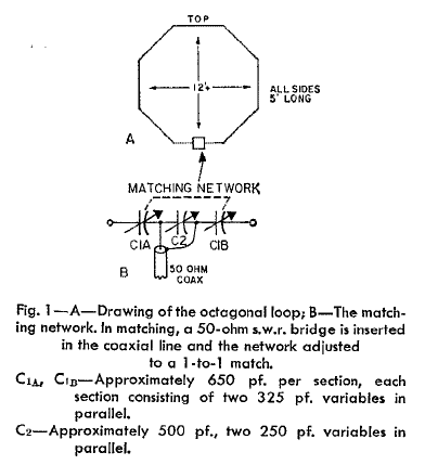
Figure 5.33(a), page 5-21 - The matching network for the loop is drawn incorrectly and in the 21st Edition, as well. Download the correct drawing here or from the original article by W1ICP in the March 1968 issue of QST.
Chapter 7 - Log-Periodic Dipole Arrays
Page 7-5, top of right-hand column: the reference to "(dashed slanted lines)" on Figure 7.B should simply be to "(slanted lines)" as only the line corresponding to an alpha value of 2 is dashed.
Chapter 11 - HF Yagi and Quad Antennas
11.2.1 Yagi Gain - fifth paragraph - when referring to "dBd", the dipole is not in free space unless the antenna for which gain is being given in dBd is also in free space. In general, dBd is a reference to the gain of a dipole located exactly at the same effective height as the comparison antenna and oriented so that its maximum gain is in the same direction as that of the comparison antenna. (Thanks, Tom W8JI)
11.4 Monoband Yagi Designs: Torque compensators are pieces of PVC tubing mounted in the same plane as and parallel to the elements by using a piece of flat aluminum plate and U-bolts as shown in Figure 11.12(A). Note that for the optimized single-band designs (sections 11.4.1-11.4.7) the torque compensator lengths are given in the printed tables ONLY and are half-element lengths just as for the other elements. i.e. - double the length and mount the compensator centered on the boom. For the optimized Hygain designs (section 11.4.8) the torque compensator dimensions are given in the associated YW file.
Table 11-8: Director 3 for the 205CA is missing. It has a spacing of 190" and the element tip is 55". Note that because the HyGain boom-to-element clamps require several inches of boom, the elements can't be mounted exactly at the end of the boom. Since the boom length of 34' is the same as the sum of element spacings, Director 3 can not have a spacing of 190" and will have to be a few inches less. This does not result in a significant change in antenna pattern according to designer N6BV.
Table 11-9: The Hy-Gain 155BA antenna boom length is 26 feet, not 24 feet.
(Thanks, Tom K1KI)
The YW files for some of the modified Hygain antennas are missing some information due to lines in the file having been dropped. Here are the correct versions of the file. No other files need to be replaced. Place these files in your YW_Yagis for Windows folder and rename them to use the YW extension (i.e. - BV105CA-Complete.YW).
When using "Save As" to store a modified YW file the program sometimes leaves out a line of the notes. Check the updated file by using a text editor such as Notepad to be sure all the information is saved correctly or to make corrections.
(Thanks, Dean N6BV)
Chapter 12 - Broadside and End-Fire Arrays
Section 12.3.1: In the fourth set of binomial element currents, the coefficient for x should be 4, not 6. (Thanks, Tom NC6B)
Chapter 15 - VHF and UHF Antenna Systems
In Tables 15-19 and 15-20 for the 22- and 33-element 432-MHz Yagis, the second column data is position from the end of the boom, not from the reflector. The original design and construction articles from QST by K1FO are downloadable for additional reference. (Part 1 and Part 2)
Chapter 17 - Antennas for Space Communications
Figure 17.20: add the note “g » 0.12-0.13 λ”
Chapter 23 - Transmission Lines
In section 23.2.5 (page 23-12) - references to Equations 8 and 17 should be to Equations 9 and 18, respectively. (Thanks, Martyn, GW6ITJ)
Figure 23.30 - N connector assembly: For assembly of the common 82-202 versions of the N connector, dimension a should be 0.315 in for a and 0.177 in for c. www.AmphenolRF.com should be consulted for exact assembly instructions of any Amphenol connector. The dimensions in the table are for Amphenol connectors only.
Chapter 25 - Antenna Materials and Construction
Figure 25.1: change “Half Span” to “Span” in the graphic (ANT0756) and the caption.
Chapter 27 - Antenna and Transmission Line Measurements
Equation 21: All four equations should have minus signs between the coefficient (a1, a2, b1, b2) and the fraction. (Thanks, Tom K8EBR)
CD-ROM Supplemental Files
Smith Chart Calculations - the PDF file shipped with the CD-ROM has some transposed text and mis-formatted equations. This version (click here to download the file) corrects those problems.
-
22nd Edition - Errata and Corrections (2nd Printing)
The following items were noted after the 2nd Printing was released. It is highly likely that the same errors exist in the 1st Printing, as well.
Chapter 1 - Antenna Fundamentals
In the equation for free-space wavelength giving λ=299.7925 x 10⁸ / f, the exponent should be 6, not 8.
Chapter 26 - Building Antenna Systems and Towers
Figure 26.31, page 26-26: Step 2 of the bowline should show the final wrap of the rope's tag end going around the main line ("around the tree") and then crossing over the first loop. The correct method of tying the knot is shown at www.animatedknots.com/bowline.
Technology >> ARRL References >> ARRL Antenna Book Reference 22nd Edition


